miniRT — Building a Ray Tracer from Scratch
In miniRT, we built a ray tracer from scratch in C. The renderer generates images by simulating rays of light travelling through a virtual 3D scene, computing intersections with objects, and calculating how light interacts with surfaces.
From rendering simple spheres, the project gradually evolved into a more complete rendering system supporting complex geometry, multiple light sources, procedural textures, bump mapping, and interactive camera controls.
The Rendering Pipeline


At a high level, the renderer works by casting rays from a virtual camera through every pixel on the screen.
For every pixel, the renderer generates a primary ray from the camera position and traces it through several stages of the rendering pipeline:
- Determine the closest object intersected by the ray
- Compute surface information such as normals and material colour
- Apply lighting calculations including ambient and diffuse shading
- Cast shadow rays to test whether light sources are occluded
- Apply additional surface effects such as textures or bump mapping
- Combine all lighting contributions into the final pixel colour
This process is repeated for every pixel in the framebuffer to produce the final rendered image.
Renderer Capabilities
Over the course of development, the renderer grew from a basic ray tracer into a more complete lighting and shading system supporting:
Geometry
|
Lighting
|
Surface Effects
|
Rendering & Interaction
|
Building a 3D Camera
One of the first major challenges was understanding how a virtual camera actually works.
To generate rays correctly, the renderer needed to understand which direction the camera was facing, what counted as “up”, and how pixels on the screen mapped into directions in 3D space. This effectively created a local coordinate system for the camera using forward, right, and up vectors.
Even when the mathematics appeared correct, small mistakes in the camera basis could produce visually plausible but incorrect scenes. At one point, rotating the camera by 180° appeared to work, except the entire scene became mirrored rather than rotated correctly. Debugging this required revisiting how the camera basis vectors were constructed and how rays were transformed into world space.
Many of the hardest bugs in the renderer were mathematically subtle rather than syntactically complex. Small mistakes in normals, rotations, or coordinate transforms could still produce scenes that looked “almost right” while being fundamentally incorrect underneath.


Ray-Object Intersections
Once the camera and ray generation were working, the next step was determining what each ray actually hit in the scene.
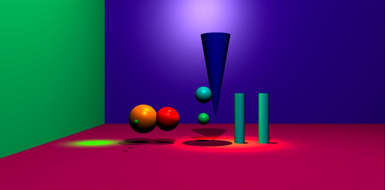
This involved checking intersections between rays and the various geometric objects in the world. The calculations differed depending on the type of object:
- spheres used quadratic equations
- planes relied on linear intersection calculations using surface normals
- cylinders and cones required constrained quadratic systems that accounted for finite object bounds and end caps
At a high level, most intersection problems followed the same pattern: describe the surface mathematically, substitute the ray equation into that surface equation, and solve for the intersection point.
In practice, however, implementing these intersections correctly was far more subtle. Small mistakes in normals, coordinate transforms, or finite object bounds could produce disappearing geometry, incorrect lighting, or visually distorted scenes.
Edge cases became especially important when dealing with finite objects. For example, a ray might intersect the infinite mathematical surface of a cylinder while missing its finite height bounds, or intersect the curved surface without hitting the end caps. Rays grazing a surface tangentially or originating extremely close to an object also introduced floating-point precision issues.
Lighting and Shadows
Once intersections worked, the next step was making scenes actually look three-dimensional.
For every visible surface point, the renderer evaluates how each light source contributes to the final colour. This involves casting rays from the intersection point toward each light source to determine:
- the angle between the light and the surface
- whether the light is blocked by another object
- how strong the contribution should be
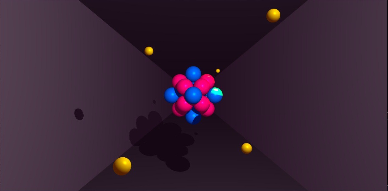
Light sources could also have different colours, allowing different parts of a scene to tint surfaces differently depending on the lighting configuration and material colours.
These contributions were then combined using several lighting components.
Ambient Lighting
A base illumination applied globally to avoid completely black shadows.
Diffuse Lighting
Diffuse shading simulates how directly a surface faces a light source. Surfaces facing the light appear brighter, while surfaces facing away receive less illumination.
This relies heavily on surface normals and dot products.
Specular Highlights
We also implemented Phong shading to simulate specular highlights, allowing shiny surfaces to produce concentrated reflections from light sources.
Shadows
If another object intersects the ray before it reaches the light source, that light does not contribute to the surface point, producing a shadow.
Lighting calculations also introduced several rendering artifacts. One recurring issue was shadow acne, where surfaces incorrectly shadowed themselves due to floating-point precision errors and rays originating too close to the surface. Fixing these issues required carefully offsetting secondary rays and handling numerical tolerances throughout the renderer.


Textures and Surface Effects
As the renderer became more stable, I began exploring techniques that improved the visual richness of scenes beyond basic geometry and lighting.
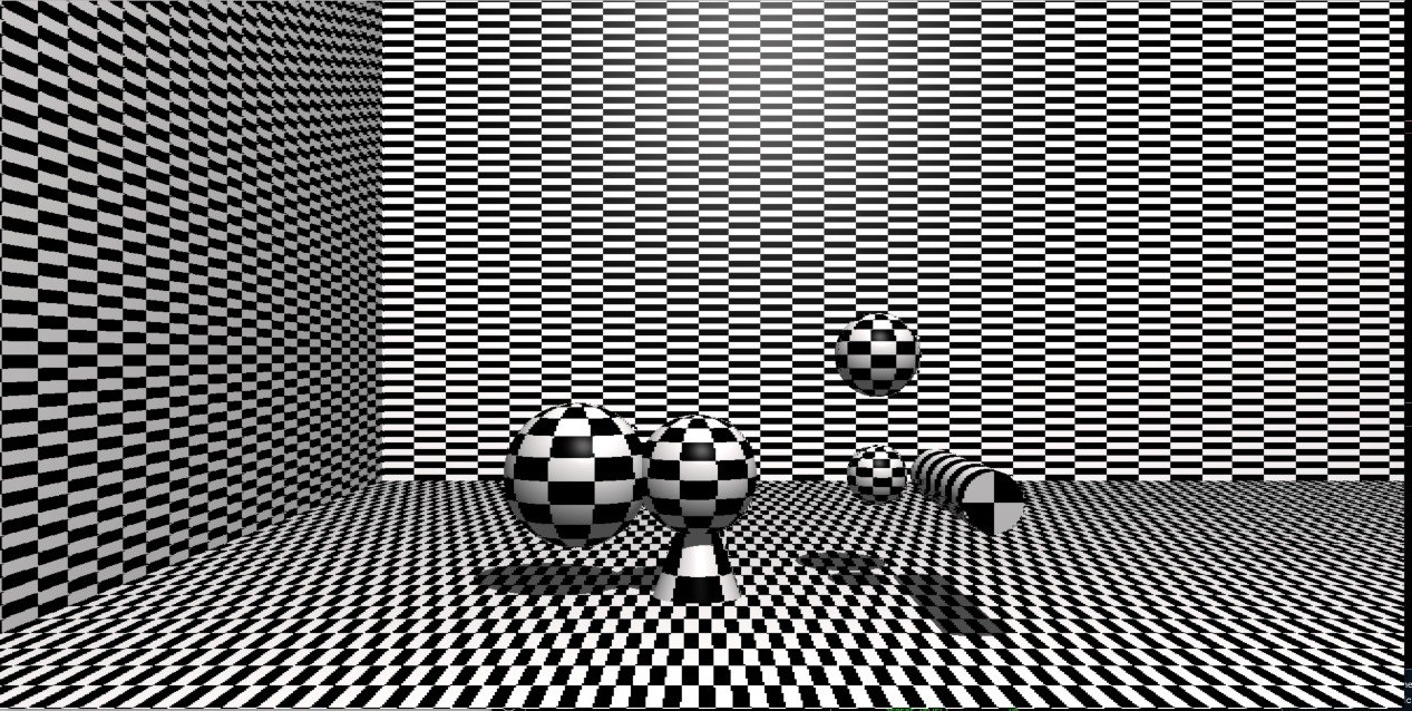
Checkerboard Textures
I implemented configurable checkerboard textures on planes, spheres, cylinders, and cones. This required mapping points on 3D surfaces into texture-space coordinates while handling repeating patterns across curved geometry.
Applying patterns to curved objects became especially interesting because the mapping needed to account for angular coordinates and wrapping behaviour.
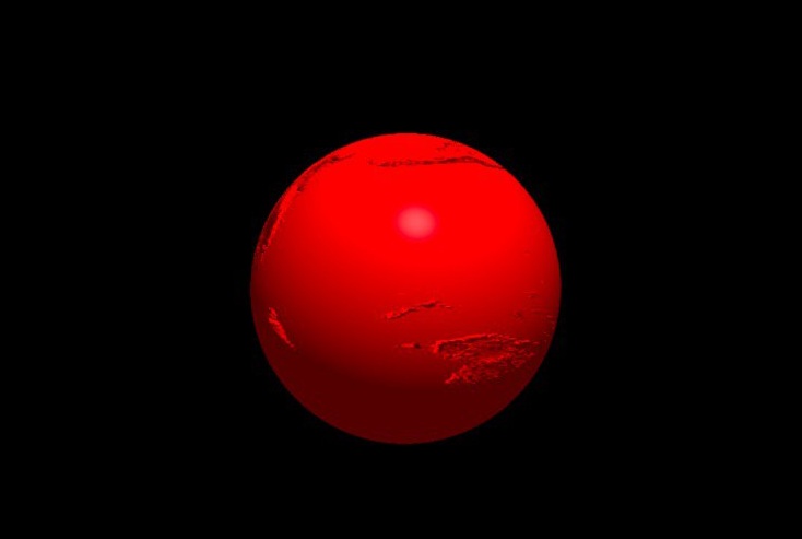
Bump Mapping
We later extended this work into bump mapping using XPM texture files.
Instead of modifying geometry directly, bump maps alter surface normals during lighting calculations to create the illusion of additional surface detail.
Implementing bump mapping required:
- UV mapping
- tangent and bitangent calculations
- transforming normals between coordinate spaces
- integrating perturbed normals into the lighting pipeline
Implementing checkerboard textures also influenced later work on bump mapping, since both features required mapping surface coordinates into texture space. As the renderer evolved, earlier systems increasingly became reusable building blocks for more advanced rendering effects.
Performance and Interaction
As the renderer became more interactive, performance became increasingly important. Features such as camera movement, object manipulation, object rotation, and light positioning made it possible to explore scenes and debug rendering behaviour in real time, but repeatedly recomputing full renders quickly became expensive as scenes grew more complex.
To make iteration smoother, we implemented lower-resolution preview rendering modes together with interpolation techniques to reconstruct skipped pixels and reduce rendering cost during development.
This included bilinear interpolation and directional interpolation passes to approximate missing pixel data while preserving overall scene structure and lighting continuity.
These preview modes became especially useful during debugging, since many rendering artifacts only became obvious once scenes were explored from different angles, object positions, and lighting configurations.
What I Learned
This project fundamentally changed how I think about graphics systems.
Before miniRT, rendering engines felt opaque and almost magical. Building one from scratch forced me to understand how images emerge from layers of geometry, lighting, coordinate systems, and mathematical transformations working together.
What surprised me most was how fragile rendering systems could be. Tiny mistakes in normals, rotations, or floating-point calculations could completely distort a scene while still producing images that looked superficially plausible. Many of the hardest bugs were not large architectural problems, but subtle mathematical errors hidden deep inside the rendering pipeline.
The project also changed the way I think about abstraction and system design. Features that initially seemed unrelated, such as checkerboard textures and bump mapping, eventually shared common foundations in texture-space mapping and coordinate transforms. As the renderer evolved, earlier systems increasingly became reusable building blocks for more advanced rendering effects.
More broadly, miniRT became one of the first projects where mathematics became immediately visible. A single incorrect vector calculation could completely distort the rendered world, while a small lighting improvement could dramatically change the realism of a scene.
Unlike many other programming projects, rendering provided immediate visual feedback: even small mathematical changes could dramatically alter the final image. That tight feedback loop between math, code, and visuals made this one of the most rewarding and conceptually satisfying projects I have worked on.